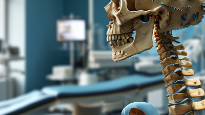
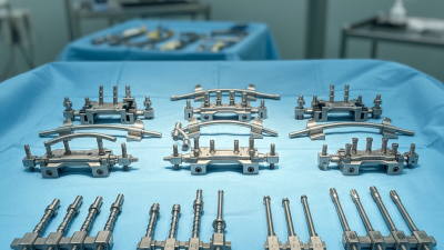
A Spinal implant design process begins with a clinical problem, not a drawing. A device must fit real anatomy, support the intended spinal segment, and work with the surgeon’s approach. Small details matter: screw trajectory, rod contour, surface finish, and access to imaging can affect use in the operating room. The design must also account for material behavior, fatigue, sterilization, and the body’s response over time. There is no shortcut.
Spine surgeon Dr. Richard Guyer offers a useful clinical perspective. Paraphrased, rather than presented as a verbatim quotation: “An implant should serve the patient’s function and the goals of treatment.” That principle keeps engineering choices tied to clinical needs. It also leaves room for hard questions. Does the design address a defined need? Can its performance be tested? Will surgeons handle it as intended? A promising concept is not proof of a safe or effective device.
This guide follows seven practical steps, from defining requirements and studying anatomy to prototyping, verification, and design refinement. It highlights choices teams can document and review, including load paths, fit, usability, and test conditions. The process is rarely perfectly linear. A prototype may expose a poor instrument angle or an assumption that needs rethinking. That is useful evidence, not failure. Clear records and input from engineers, clinicians, and quality specialists help teams evaluate trade-offs carefully. The aim is a design grounded in clinical needs and supported by appropriate testing—not a claim that any implant suits every patient.
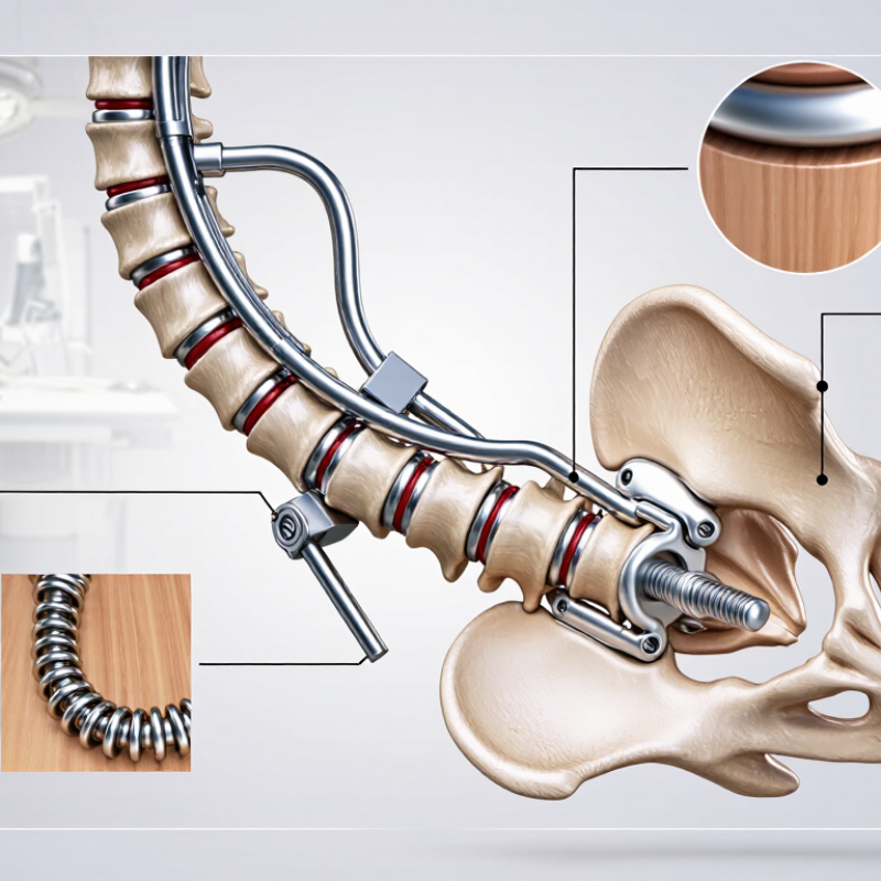
Defining clinical needs and anatomical requirements gives spinal implant design a practical starting point. The intended procedure, spinal level, and patient population shape what the device must do. Surgeons, engineers, and imaging specialists can identify requirements together. They should consider fixation, alignment, access, and the possibility of revision. A lumbar construct, for example, must fit around nearby nerves while allowing the planned surgical approach. Small differences matter. Bone quality and individual anatomy can change how a design performs.
Anatomical assessment should use appropriate imaging and account for variation, not just an average measurement. Vertebral dimensions, curvature, and available screw paths can inform implant geometry. Designers also need to consider how instruments reach the site and whether the implant can be positioned as intended. A narrow corridor may limit placement. But images do not capture every condition encountered during surgery. That uncertainty deserves attention.
Clinical needs become useful design inputs when they are specific and testable. “Support stability” is too broad on its own; teams should clarify the relevant loads, motion, and evaluation methods. Requirements should also address material compatibility, visibility on imaging, and handling during implantation. Not every preference can be reconciled. It is worth revisiting assumptions when clinical feedback conflicts with a proposed feature, rather than treating the first specification as settled.
Selecting implant materials starts with the intended spinal level, load, and patient anatomy. Titanium alloys are valued for strength and corrosion resistance, while radiolucent polymers can make postoperative imaging easier to interpret. Neither option is automatically best. The choice depends on the implant’s role and how its properties interact with surrounding bone. A screw’s thread shape, for example, must support fixation without creating excessive stress in the vertebra. Small details matter.
Design constraints extend beyond material strength. Engineers must consider fatigue under repeated motion, wear at contacting surfaces, sterilization, and manufacturing tolerances. Imaging needs matter too: dense components may obscure nearby structures, complicating follow-up assessment. Bench tests can reveal weak points, but they cannot fully reproduce varied anatomy or years of movement. That gap deserves attention. A clean CAD model may conceal an awkward fit or a stress concentration near a connector. Design reviews should include clinical input, documented test methods, and careful evaluation against relevant standards. Trade-offs remain, and a promising prototype is not proof of long-term performance.
Spinal implant geometry starts with a defined design brief, not a shape that simply looks plausible. The brief may specify the anatomical region, implant footprint, height range, fixation method, and intended loading conditions. Imaging can help engineers map relevant anatomy, but measurements require careful review because patient position and image resolution affect interpretation. Small details matter. Edge radii, contact surfaces, and insertion features can influence fit and handling. These choices should be discussed with clinicians and checked against the intended use.
In CAD, the team turns those requirements into a three-dimensional model with clear dimensions and controlled tolerances. The model should show how components align and how the implant interfaces with surrounding anatomy. Engineers also consider whether the geometry can be manufactured consistently; a narrow internal feature may look useful on screen yet prove difficult to produce or inspect. Not always obvious. Simulation can flag stress concentrations or weak regions, but it does not replace physical testing or clinical judgment. Early models are rarely perfect, and even a polished surface can hide an awkward fit. Revising the geometry after design reviews is part of responsible development, not a sign that the process failed.
Prototyping should test the spinal implant as a physical device, not just a polished CAD model. Build early samples with production-representative materials and surface finishes; small changes can alter stiffness or create stress concentrations. ASTM F2077 outlines mechanical tests for intervertebral body fusion devices, including compression, compression-shear, torsion, and fatigue. Record load-displacement curves, stiffness, cycle count, and failure location. ASTM F2267 addresses subsidence testing, helping teams compare how designs respond to compressive loading against a defined test setup. These standards guide measurement; they do not establish a universal pass mark or predict clinical outcomes.
A useful test report links each result to the specimen, fixture, loading direction, and failure mode. Repeat tests across multiple samples, then compare the spread—not only the best result. Check whether a crack begins near a porous feature, whether an endplate deforms, or whether the implant slips in the fixture. Fixture alignment matters. A small angle error can distort the data. Bench testing also has limits: bone quality, surgical placement, and healing vary in patients. That gap deserves honest attention, not a confident headline.
Tips: Photograph each failed specimen before disassembly. Keep one prototype unchanged as a control, and document every design revision. If a result looks surprisingly strong, verify the setup before celebrating.
| Step | Design focus | Prototype and evaluation activities | Useful outputs and decision criteria |
|---|---|---|---|
| 1. Define intended use and design inputs | Specify the spinal region, intended patient population, implant function, surgical approach, and anatomical constraints. | Review clinical and anatomical requirements; identify expected load directions, fixation interfaces, and foreseeable use-related risks. | A traceable design-input list, preliminary acceptance criteria, and documented risk-management inputs. Requirements should match the intended device and use. |
| 2. Develop concepts and select materials | Balance anatomical fit, stability, surgical access, imaging needs, and manufacturability. | Compare CAD concepts and interface geometries. Assess candidate materials and manufacturing routes against mechanical, biological, and use requirements. | A selected concept with documented trade-offs, material rationale, and identified design risks. Material suitability depends on the finished device and its contact with the body. |
| 3. Build and inspect early prototypes | Check geometry, assembly, interfaces, and practical manufacturability before formal verification. | Produce prototypes using suitable methods; inspect critical dimensions, features, surface condition, and assembly fit. Record prototype material and process differences from the planned finished device. | Inspection records and a prioritized list of design changes. Early prototypes are useful for iteration but may not represent final-device mechanical performance. |
| 4. Evaluate static mechanical performance | Determine how the implant or construct responds to relevant loads and identify potential weak points. | For intervertebral body fusion devices, ASTM F2077 includes mechanical test methods such as static compression, compression-shear, and torsion. ASTM F2267 describes a static subsidence test method for these devices. Select methods according to device type and intended use. | Load-displacement data, observed failure modes, and comparisons against predefined criteria. Test configuration and acceptance limits should be justified for the specific design. |
| 5. Assess fatigue and cyclic durability | Investigate performance under repeated loading and characterize the location and mode of failure. | Use an appropriate cyclic test method and a documented, device-relevant test setup. ASTM F2077 includes dynamic test methods for intervertebral body fusion devices; spinal fixation constructs may require different applicable methods, such as ASTM F1717. | Cycles to failure or completion, test conditions, failure location, and specimen observations. Results apply to the tested setup and should not be generalized beyond it. |
| 6. Evaluate fit and simulated surgical use | Confirm that the implant can be positioned and handled as intended within relevant anatomical constraints. | Assess representative anatomical models or other justified setups for placement, tool access, interface engagement, and visibility under relevant imaging conditions. Use simulated-use or anatomical evaluations appropriate to the device. | Documented fit, placement, and handling observations, plus any required changes to geometry or instruments. This evaluation complements, rather than replaces, mechanical testing. |
| 7. Iterate, verify, and document the design | Confirm that the final design meets its inputs and that identified risks have been addressed. | Update the design based on test findings; repeat affected evaluations on representative devices; maintain traceability among requirements, methods, results, and design changes. | A verification record, resolved or controlled risk items, and a justified design baseline. Applicable standards and their current editions should be confirmed for the device and regulatory context. |
Note: ASTM methods listed are examples, not a complete test plan. Applicability, specimen configuration, test conditions, and acceptance criteria should be selected and justified for the specific implant.
Spinal implant design is not complete when the geometry looks right on screen. Engineers need to connect each design requirement to a measurable safety check. For example, fatigue testing can examine repeated loading, while simulated-use testing can reveal handling problems around small instruments. Material and biological evaluations should match the implant’s intended contact and duration. Document assumptions, too. They can change.
Manufacturing checks matter just as much. Confirm that critical dimensions remain within defined tolerances across production runs, not only on a carefully made prototype. Review cleaning, surface finishing, inspection methods, and process controls before design release. Then map test evidence and risk controls to the regulatory requirements of each intended market. Keep records traceable, including design changes and their impact on earlier results. A missed step can be costly.
Tips: Use a clear verification matrix linking each requirement to a test, acceptance criterion, and record. Involve manufacturing and quality specialists early. Repeat tests when a material, process, or dimension changes. No plan is perfect; review unexpected results rather than explaining them away. A practical design should be safe, reproducible, and supported by evidence.